Smart Plant Monitoring System
The inspiration for this project came to my mind reminding the flower pots in garden in my house.I am fond of flower plants.I bring various fascinating flower plants from other places where ever i visit.So they are close to my heart and and need special care like.....
-
Timely water
-
Save from intruing animals
-
Ligting at night and more....!!
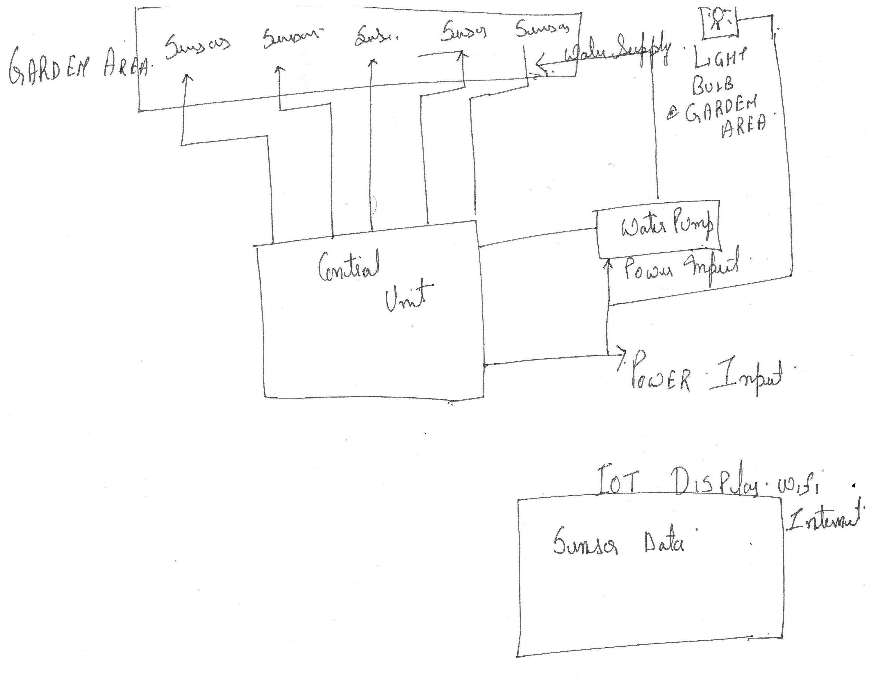
To solve this problem this project came to my mind. The flowchart of this project
The components required for this project;-
| S No | Description | Image |
| 01 | ESP 8266 Node MCU | 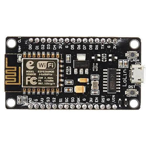 |
| 02 | CD74HC4067 16-Channel Analog Digital Multiplexer Breakout Board Module | 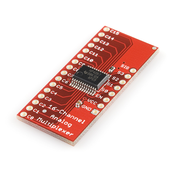 |
| 03 | Generic 5V 10A 2 Channel Relay Module | 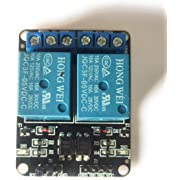 |
| 04 | DHT11 Digital Temperature Humidity Sensor Module | 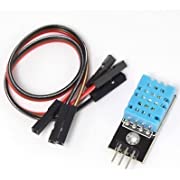 |
| 05 | TE215 Dual Mode High Sensitivity Soil Moisture Sensor, 3.3V-5V | 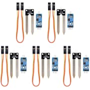 |
| 06 | LM393 Optical Photosensitive LDR light sensor module 3-5V | 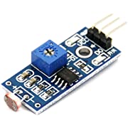 |
| 07 | DC 5V Submersible motor Pump | 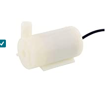 |
| 08 | 1/4 Inch Inlet/Outlet Diaphragm Solenoid Valve | 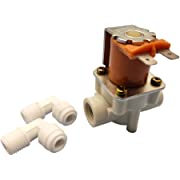 |
| 09 | Pipe Tube 1/4" | 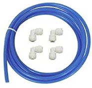 |
| 10 | 1/4" Connectors For Pipe tube | 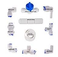 |
| 11 | 5 V Regulated Power Supply ,Some LEDs ,and Jumper Wire |
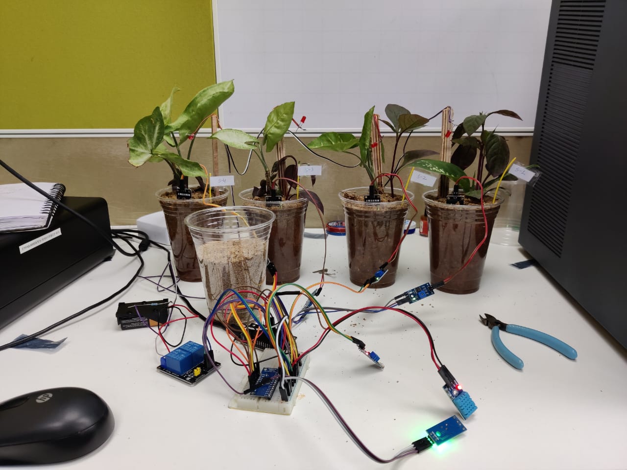
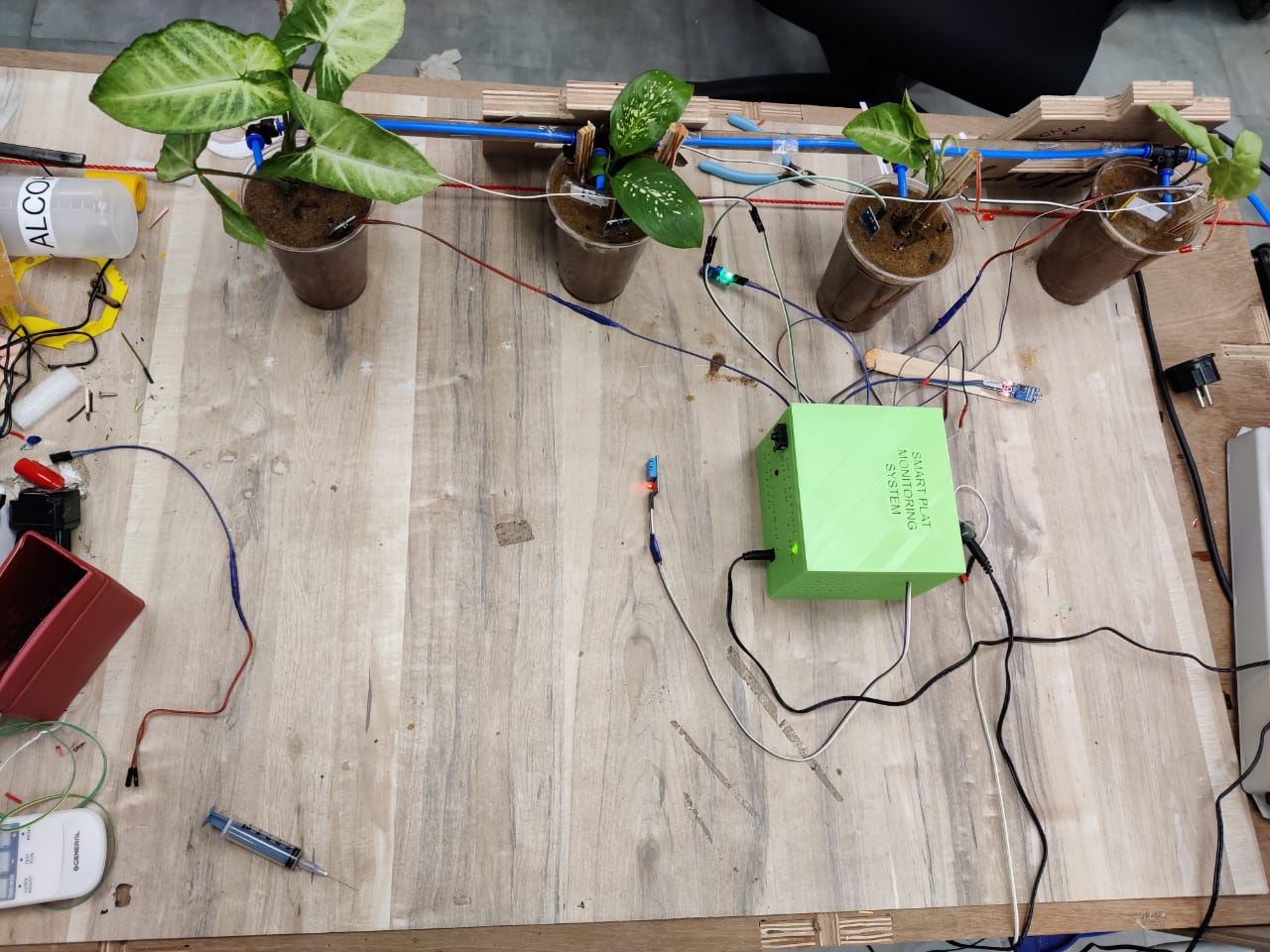
This is IoT based project.Monitors the soil moisture,temperature, humidity and intruders near the plants area.It turns on the motor pump when the moisture level goes below the marked level.When there is not optimum light near the palnt area it triggers the bulb/led through the relay using the LDR module. It also make sound when any itrudeering animal/monkeys are found there.
It also give the live status of the controlling parameters through wi-fi over the internet which can be monitored from any where.
The crust of the project is Node MCU ESP 8266 Wi Fi Module.It is used the tranmitt data collected from various sensors to the user on the desktop/laptop thorough the computer network using the Adafruit library.
If The Soil Moisture or humidity level near the plant goes below the decided level the node mcu triggers the motor pump for water supply through the relay module.The LDR is used to sense the day and light condition near the plants and it triggers the bulb (In my case LED) through the relay module.
The DHT 11 sensor is used to monitor the temperature and humidity levels near the plants.
The node MCU has only one analog pin ,but i am requring the more no of analog pins,so i have used the 16x1 channel analog/digital cmos multiplexer 74HC4067 with Node MCU.(Ref:-https://protosupplies.com/product/16-ch-analog-digital-mux-module/)
In this system the ESP 8266 Node MCU Plays the main role.The Soil sensors are connected to the analog pin A0 of the node MCU via a CD74HC4067 16-Channel Analog Digital Multiplexer.The need of the CD74HC4067 16-Channel Analog Digital Multiplexer arised because the there is only one analog pin in the ESP 8266 node mcu.
The LDR is also connected to the Digital Multiplexer.In this system when the nodemcu when ever detects the low moisture in the pots it triggers submersible water pump connected to the digital pin D5 and supplies the water to the pots and when the moisture in the pots is reched to the sufficient level the pump is switched off.
One LDR is also connected to the digital C4 pin of the multiplexer .when this sesor detects the low light or dark in the pots area it triggers the relay connected to the D7 pin of the node mcu and switchs on the light.
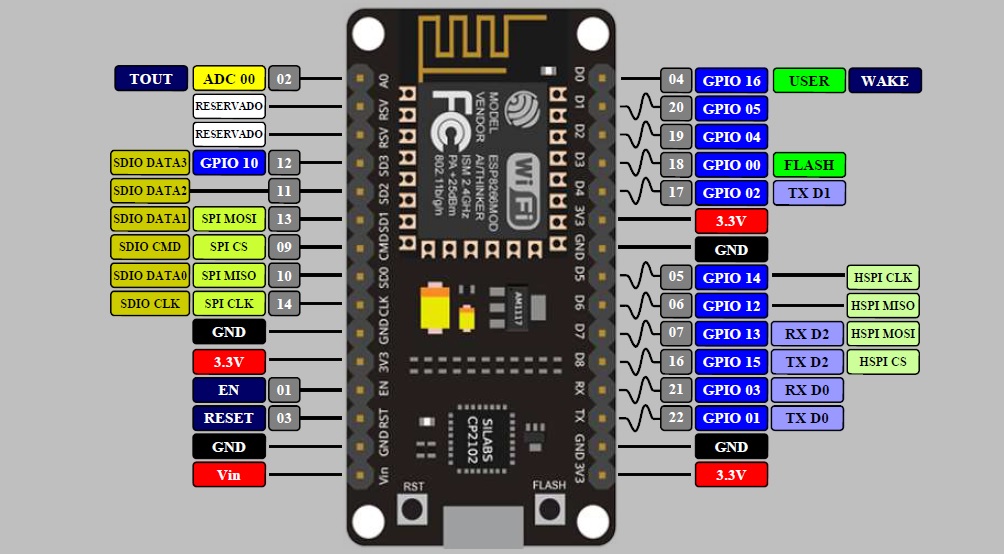
The pin out diagram of the NODE MCU is as follows:-
The Bill of materials for this project is:-
| Sno | Components | Price (Rs) |
| 01 | -ESP 8266 Node MCU | 300 |
| 02 | -CD74HC4067 16-Channel Analog Digital Multiplexer Breakout Board Module | 200 |
| 03 | -Generic 5V 10A 2 Channel Relay Module | 100 |
| 04 | -DHT11 Digital Temperature Humidity Sensor Module | 150 |
| 05 | -TE215 Dual Mode High Sensitivity Soil Moisture Sensor, 3.3V-5V X 5 | 500 |
| 06 | -LM393 Optical Photosensitive LDR light sensor module 3-5V | 70 |
| 07 | -DC 5V Submersible motor Pump | 80 |
| 08 | -1/4 Inch Inlet/Outlet Diaphragm Solenoid Valve | 350 |
| 09 | -Pipe Tube 1/4" - 5 Mtrs | 30 |
| 10 | -1/4" Connectors For Pipe tube X 13 | 325 |
| 11 | -IC 7805 | 13 |
| 12 | -Heat Sink | 10 |
| 13 | -Heat Sink Paste | 20 |
| 14 | -Switch | 10 |
| 15 | Total | 2158 |
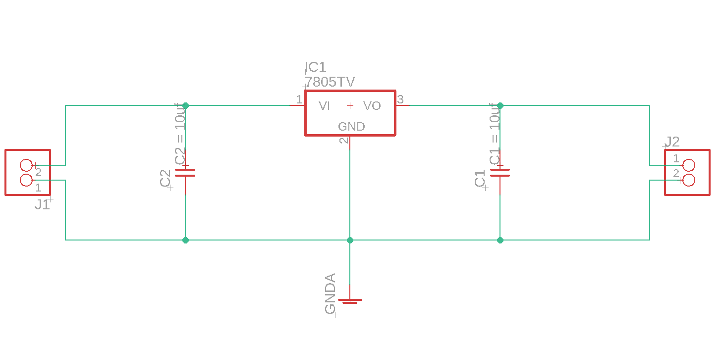
The following is the Circuit diagram :-
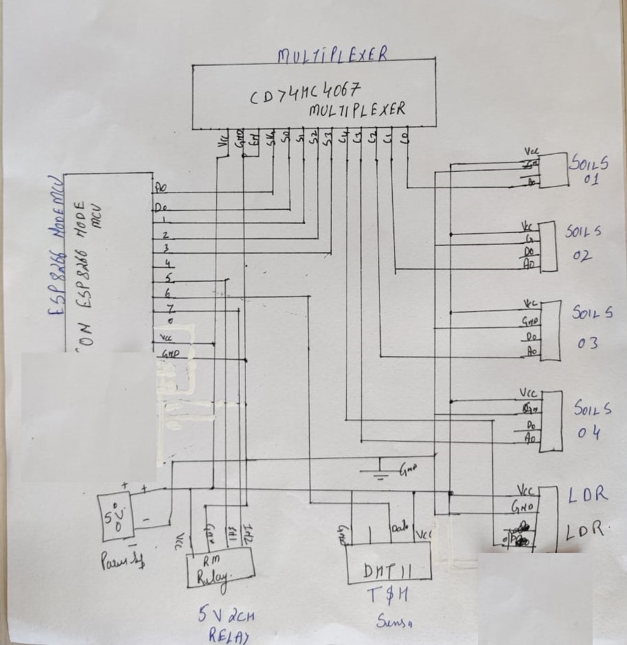
In this circuit diagram i have used the CD74HC4067 16-Channel Analog Digital Multiplexer.The need of this multiplexer arised due to the single analog pin in the node mcu.and i am using the 4 TE215 soil sensors nad one LDR module LM393 which sends the analog output.
The pin out diagram of the CD74HC4067 16-Channel Analog Digital Multiplexer is 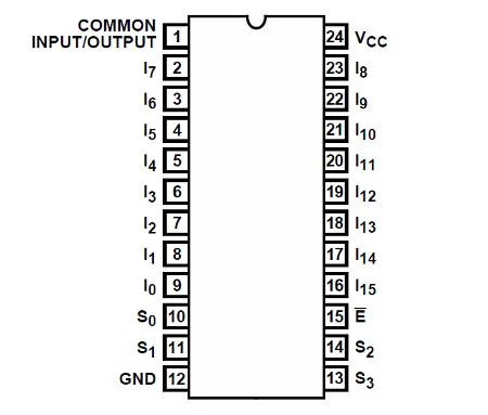
This is an an IC that can direct a flow of current in either direction from one pin to any one of sixteen pins. Another way to think abou it is that you can consider the 74HC4067 to be a digital replacement to those rotary switches that allow you to select one of sixteen positions.If for some reason you have the 74HCT4067 it can only work on 4.5~5.5V DC. Next – consider the pinout diagram from the data sheet...
The power supply for the part is applied to pin 24, and GND to … pin 12. Pin 15 is used to turn the control the current flow through the inputs/outputs – if this is connected to Vcc the IC stops flow, and when connected to GND it allows flow. You can always control this with a digital output pin if required, or just tie it to GND if this doesn’t matter.
Next – pin one. This is where the current either flows in to be sent to one of the sixteen outputs – or where the current flows out from one of the sixteen inputs. The sixteen inputs/outputs are labelled I0~I15.
i am using the module of CD74HC4067 16-Channel Analog Digital Multiplexer
i am using the pins (c0-c4)
The output from the multiplexer can be obtained according the following truth table.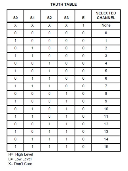
Finally there are the four control pins – labelled S0~S3. By setting these HIGH or LOW (Vcc or GND) you can control which I/O pins the current flow is directed through. So how does that work? Once again – reach for the the data sheet and review the following table in our image for this step.
Not only does it show what happens when pin 15 is set to HIGH (i.e. nothing) it shows what combination of HIGH and LOW for the control pins are required to select which I/O pin the current will flow through. If you scroll down a bit hopefully you noticed that the combination of S0~S3 is in fact the binary equivalent of the pin number – with the least significant bit first.
For example, to select pin 9 (9 in binary is 1001) you set the IC pins S0 and S3 to HIGH, and S1 and S2 to LOW. How you control those control pins is of course up to you – either with some digital logic circuit for your application or as mentioned earlier with a microcontroller.
(Credits :-https://www.instructables.com)
The datasheet of the CD74HC4067 16-Channel Analog Digital Multiplexer can be found here
I 4 soil sensor (SS1,SS2,SS4 and SS4) and LDR module are sending the signal to the C0 - C4 pins of the multiplexer.The status of these 5 sensors are selected using the S0,S1,S2,S3 pins of the multiplexer using the one signal pin which is connected to A0 pin of the NODE MCU.
I used the above truth table for extracting the signals from the five sensors
| D3-S3 | D2-S2 | D1-S1 | D0-S0 | SIG-A0 |
| LOW | LOW | LOW | LOW | C0 |
| LOW | LOW | LOW | HIGH | C1 |
| LOW | LOW | HIGH | LOW | C2 |
| LOW | LOW | HIGH | HIGH | C3 |
| LOW | LOW | LOW | LOW | C4 |
The DHT11 temp and humidity sensor data pin is connected to D6 pin of the Nodemcu.and the D5 and D7 pin of the node mcu is conncetd to the input pin of the 5v 2 channel relay.
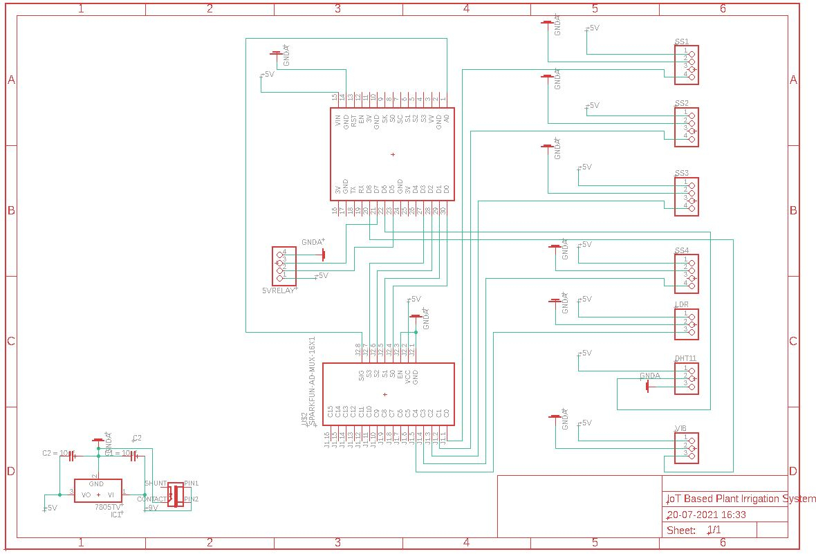
To make this project first is designed the circuit in the Autodesk eagle cad
Here is the screen shot of the circuit design.
#include#include #include "Adafruit_MQTT.h" #include "Adafruit_MQTT_Client.h" #include "DHT.h" #define DHTTYPE DHT11 #define dht_dpin D6 int sensorPin = A0; int sensorValue1 = 0; int sensorValue2= 0; int sensorValue3 = 0; int sensorValue4 = 0; int sensorValue5 = 0; #define S0 D0 #define S1 D1 #define S2 D2 #define S3 D3 #define ON_OFF D5 // Relay 1 Solenoid #define SW D7 // Relay 2 Light #define VBR D8 // Vibration #define led D4 // pump led DHT dht(dht_dpin, DHTTYPE); #define WLAN_SSID "XXXXXXXXXXXX" // SSID #define WLAN_PASS "XXXXXXXXXXXX" // password #define AIO_SERVER "io.adafruit.com" //Adafruit Server #define AIO_SERVERPORT 1883 #define AIO_USERNAME "XXXXXXXXXX" // Username #define AIO_KEY "aio_XXXXXXXXXXXXXXXXX" // Auth Key WiFiClient client; Adafruit_MQTT_Client mqtt(&client, AIO_SERVER, AIO_SERVERPORT, AIO_USERNAME, AIO_KEY); Adafruit_MQTT_Publish photocel3 = Adafruit_MQTT_Publish(&mqtt, AIO_USERNAME "/feeds/MS1"); Adafruit_MQTT_Publish photocel4 = Adafruit_MQTT_Publish(&mqtt, AIO_USERNAME "/feeds/MS2"); Adafruit_MQTT_Publish photocel5 = Adafruit_MQTT_Publish(&mqtt, AIO_USERNAME "/feeds/MS3"); Adafruit_MQTT_Publish photocel6 = Adafruit_MQTT_Publish(&mqtt, AIO_USERNAME "/feeds/MS4"); Adafruit_MQTT_Publish photocel1 = Adafruit_MQTT_Publish(&mqtt, AIO_USERNAME "/feeds/tmp"); Adafruit_MQTT_Publish photocel2 = Adafruit_MQTT_Publish(&mqtt, AIO_USERNAME "/feeds/hum"); Adafruit_MQTT_Publish photocel7 = Adafruit_MQTT_Publish(&mqtt, AIO_USERNAME "/feeds/LHT"); void MQTT_connect(); void setup(void) { pinMode(S0,OUTPUT); pinMode(S1,OUTPUT); pinMode(S2,OUTPUT); pinMode(S3,OUTPUT); pinMode(LED_BUILTIN, OUTPUT); pinMode(ON_OFF, OUTPUT); pinMode(SW, OUTPUT); pinMode(led, OUTPUT); pinMode(VBR,INPUT); Serial.begin(9600); delay(10); // Connect to WiFi access point. Serial.println(); Serial.println(); Serial.print("Connecting to "); Serial.println(WLAN_SSID); WiFi.begin(WLAN_SSID, WLAN_PASS); while (WiFi.status() != WL_CONNECTED) { delay(500); Serial.print("."); } Serial.println(); Serial.println("WiFi connected"); Serial.println("IP address: "); Serial.println(WiFi.localIP()); } void loop() { MQTT_connect(); float h =0.0; //Humidity level float t =0.0; //Temperature in celcius float f =0.0; //Temperature in fahrenheit float m =0.0; // moisture from soil sensor int i = 0; int moisture_percentage=0; // for(i=0;i<1000;i++) { h = dht.readHumidity(); t = dht.readTemperature(); // f = (h * 1.8) + 32; } digitalWrite(S0,LOW); digitalWrite(S1,LOW); digitalWrite(S2,LOW); digitalWrite(S3,LOW); sensorValue1=(analogRead(sensorPin));delay(1); digitalWrite(S0,HIGH); digitalWrite(S1,LOW); digitalWrite(S2,LOW); digitalWrite(S3,LOW); digitalWrite(LED_BUILTIN,HIGH); sensorValue2=(analogRead(sensorPin));delay(1); digitalWrite(S0,LOW); digitalWrite(S1,HIGH); digitalWrite(S2,LOW); digitalWrite(S3,LOW); sensorValue3=(analogRead(sensorPin));delay(1); digitalWrite(S0,HIGH); digitalWrite(S1,HIGH); digitalWrite(S2,LOW); digitalWrite(S3,LOW); sensorValue4=(analogRead(sensorPin));delay(1); digitalWrite(S0,LOW); digitalWrite(S1,LOW); digitalWrite(S2,HIGH); digitalWrite(S3,LOW); sensorValue5=(analogRead(sensorPin));delay(1); if(VBR==HIGH) { digitalWrite(LED_BUILTIN,LOW); } else { digitalWrite(LED_BUILTIN,HIGH); } delay(980); if(sensorValue5<350) { digitalWrite(SW,HIGH); } else { digitalWrite(SW,LOW); } Serial.println(sensorValue5); if (! photocel2.publish(h)) { } else { } if (! photocel1.publish(t)) { } else { } if (! photocel3.publish(sensorValue1)) { } else { } delay(10); if (! photocel4.publish(sensorValue2)) { } else { } delay(10); if (! photocel5.publish(sensorValue3)) { / } else { } delay(10); if (! photocel6.publish(sensorValue4)) { } else { } delay(10); if (! photocel7.publish(sensorValue5)) { } else { } delay(10); Serial.println("SENSOR VALUE 1 - "+sensorValue1); if(sensorValue1>700) { digitalWrite(ON_OFF, LOW); digitalWrite(led, HIGH); // j=1;digitalWrite(ON_OFF, HIGH); }else{digitalWrite(ON_OFF, HIGH); digitalWrite(led, LOW); // j=0;digitalWrite(ON_OFF, LOW); } } void MQTT_connect() { int8_t ret; if (mqtt.connected()) { delay(16000);//1 return; } Serial.print("Connecting to MQTT... "); uint8_t retries = 3; while ((ret = mqtt.connect()) != 0) { Serial.println(mqtt.connectErrorString(ret)); Serial.println("Retrying MQTT connection in 5 seconds..."); mqtt.disconnect(); delay(12000); retries--; if (retries == 0) { while (1); } } Serial.println("MQTT Connected!"); }
I tested the circuit using the bread board uploading the program it was working fine.
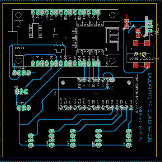
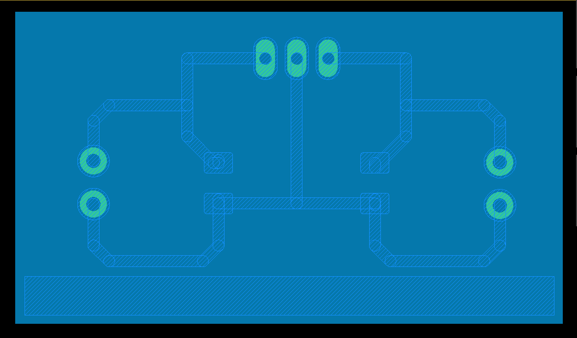
after this created the PCB using the eagle cad
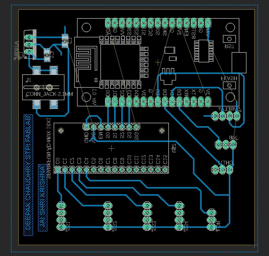
Here in the board file i added the components on the top layer (non copper layer) as i am using the female headers and traces in the lower layer (copper layer) .I added the 2.1 mm power jack to the board and and two 10 uf smd components on the copper layer.so some of the components are in the bottom layer (copper layer) and some of the components on the top (non copper layer).While switching to board file from the schematic i had to mirror the the components (2.1 mm power jack and two 10 uf smd capacitors ) where as the 7805 IC i am connection through the female header so no mirroring.refer to the following image initially the capacitors and the 2.1 mm jack are at the top layer which are to be attached to the bottom layer the image before mirroring the components is as follows.
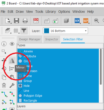
To do mirroring first click on the mirror tab and then click on the origin on the componets to be mirrored.Plz see the image below.
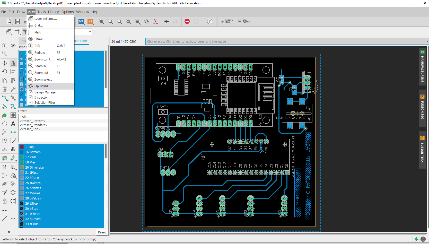
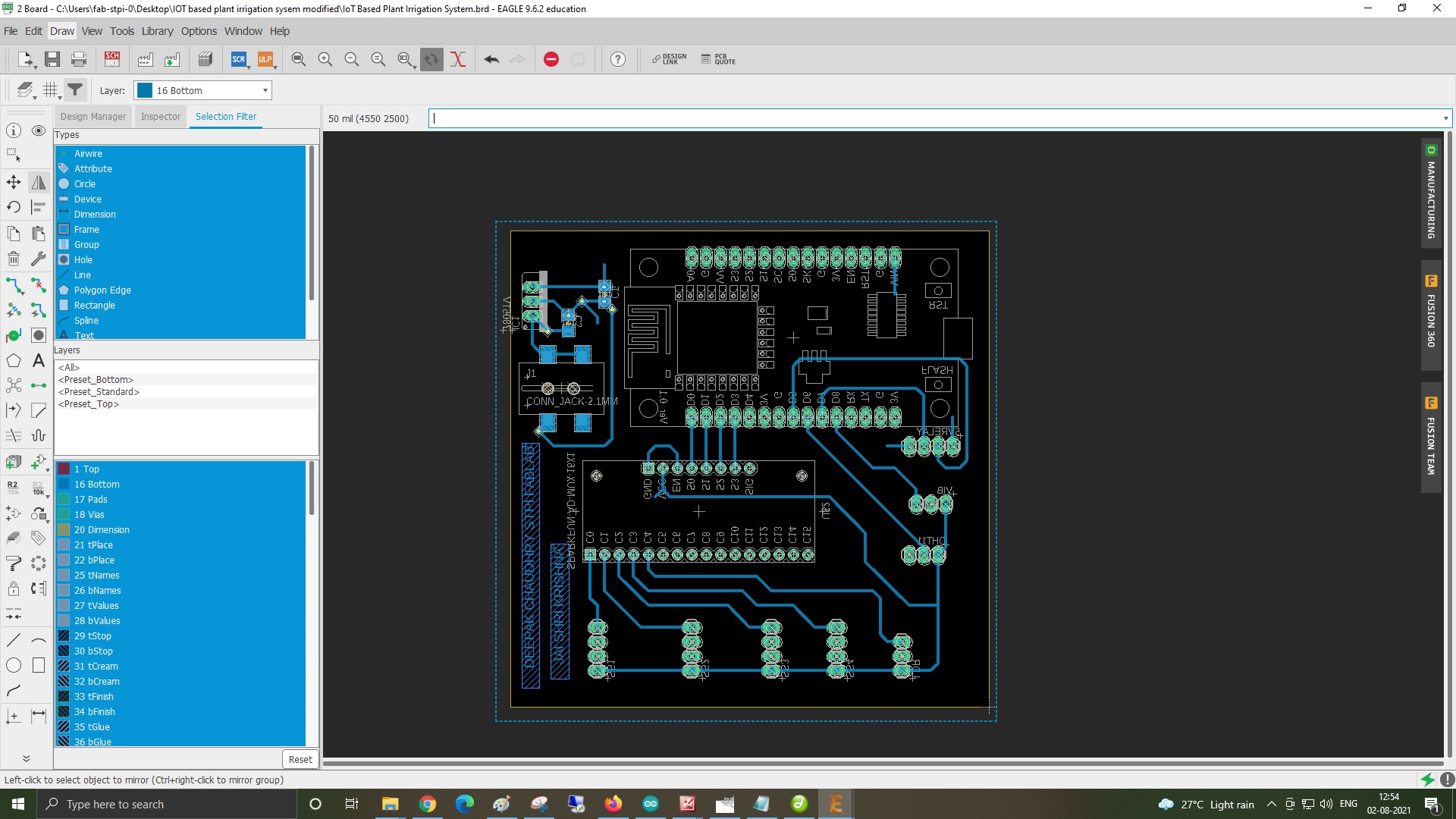
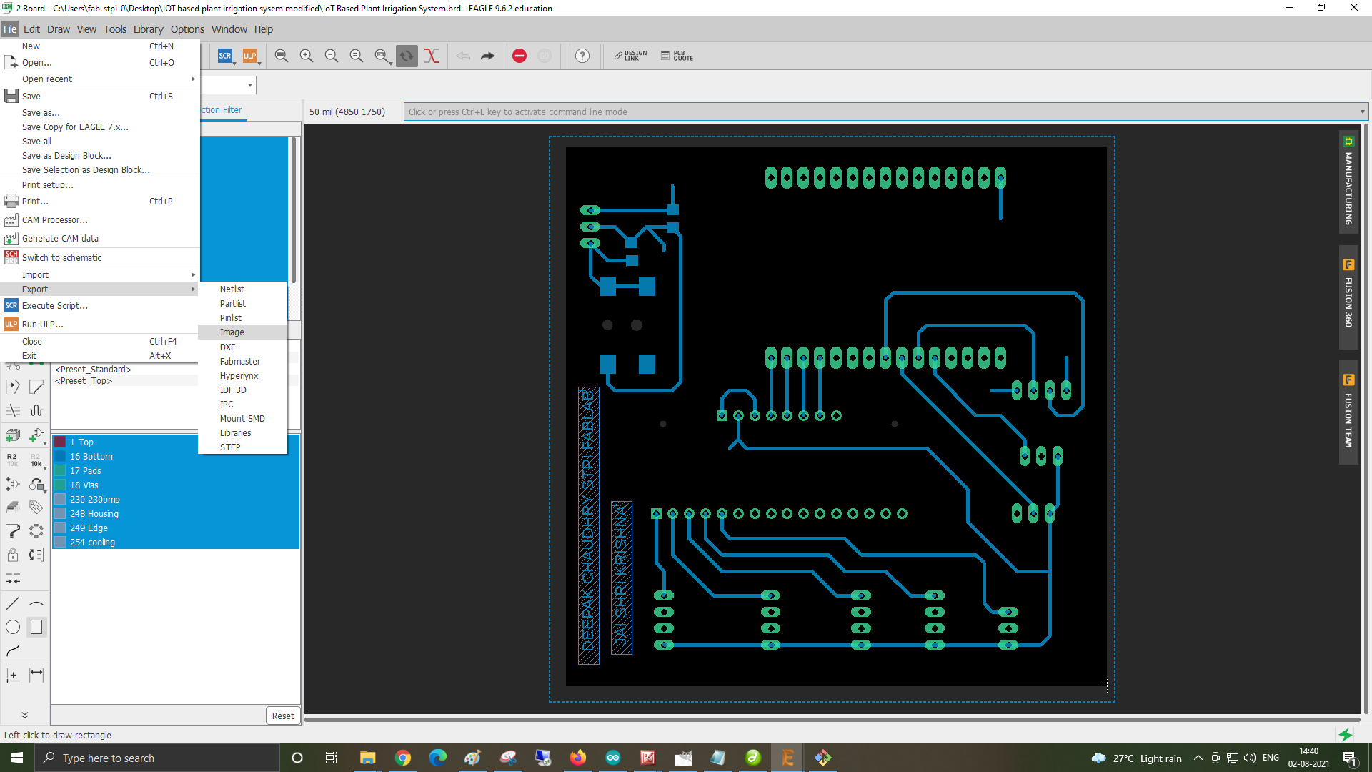
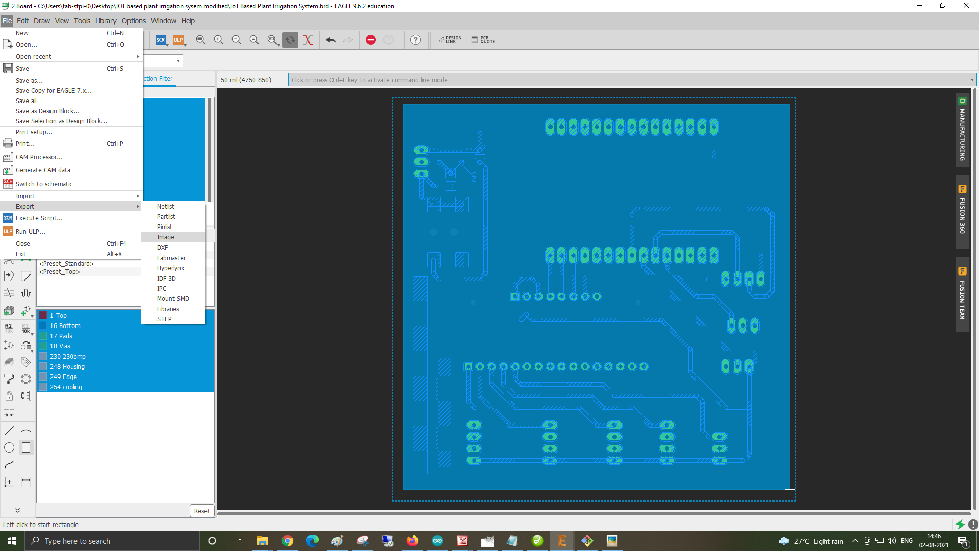
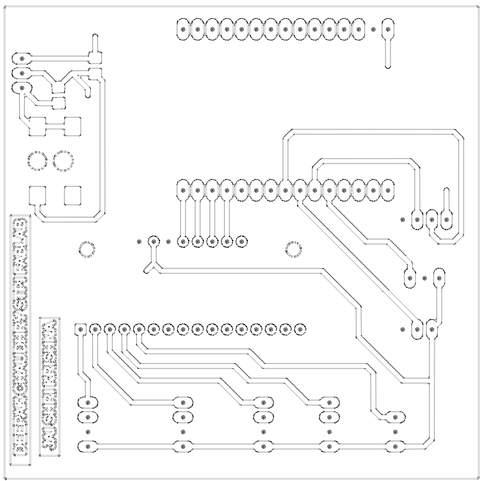
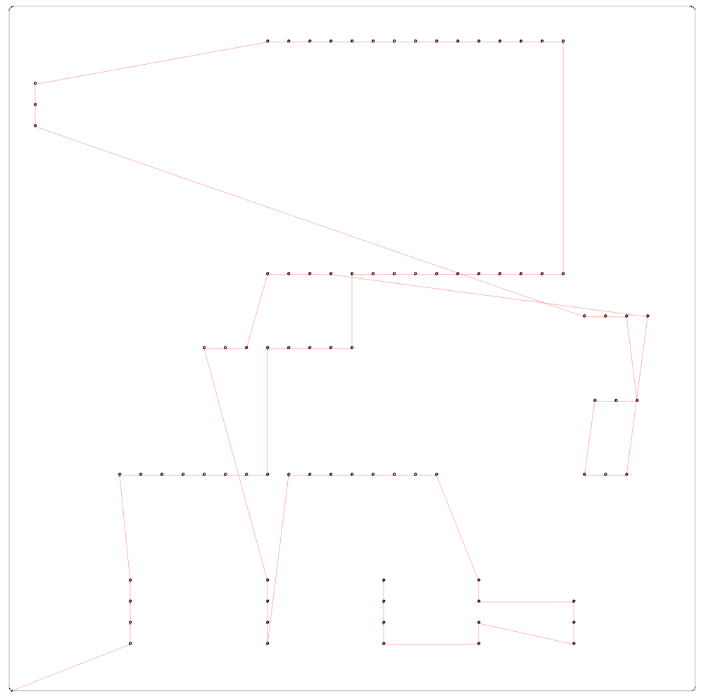
Now bfore exporting the image as png flip the image as shown in the image.other wise it will mill the as it is and find the wrong connecton to the components to be soldered.and it necessary because we are using the smd and through hole components in the board. First go to view tab in eale and then click flip and then clik on the pcb.the pcb board image will be fliped. View->Flip Board-.click on the pcb board.Refere to the images below
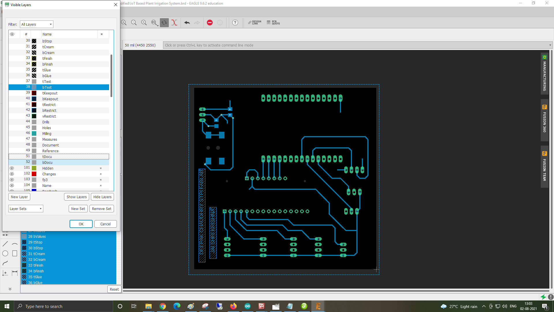
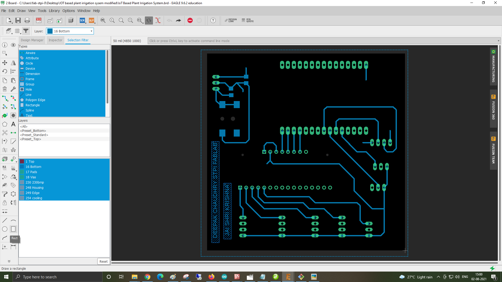
Now before exporting the pcb trace image check the dimension of the pcb trace image so that it may cut traces on the actual size of the PCB board available for milling.Before exporting click on the layers and disable dimesion,tplace,bplace,t origin,b origin,tnames,bnames,tcream,bcream,tstop,bstop,tvalues,bvalues,tglue,bglue,tkeepout,bkeepout,drill,holes,tdocu and bdocu.It means only the traces should be there.and then export
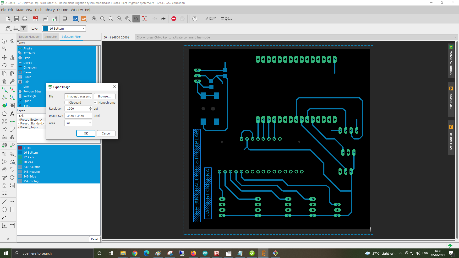
after this disble the I exported the files as png with monochrome and 1000 dpi.
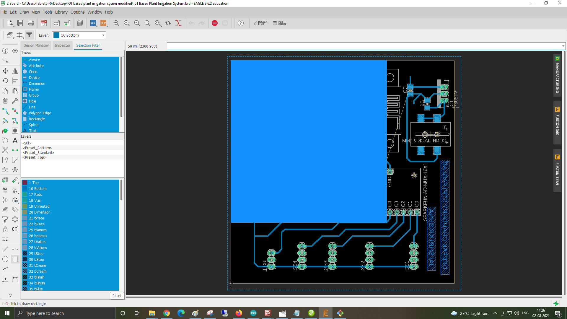
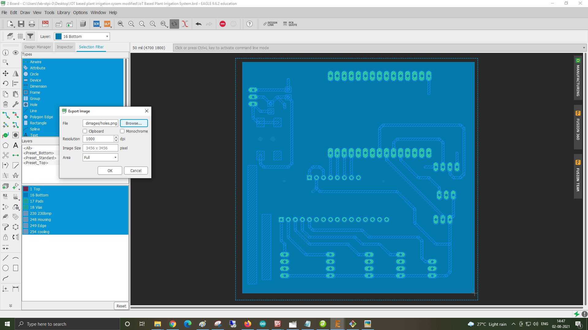
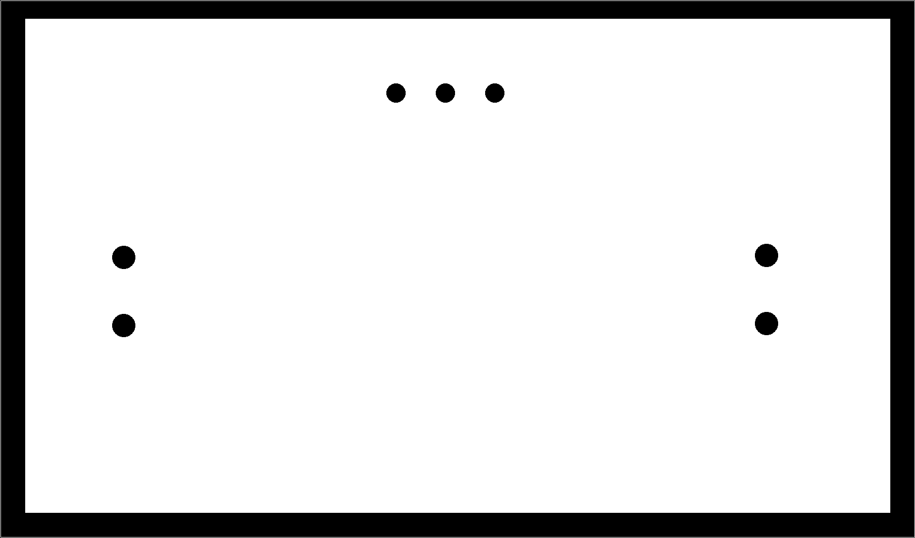
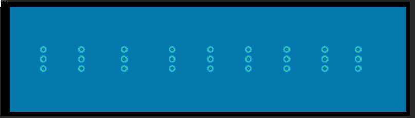
For exporting the holes file from Eagle cad. select the bottom layer from the tab as shown in image
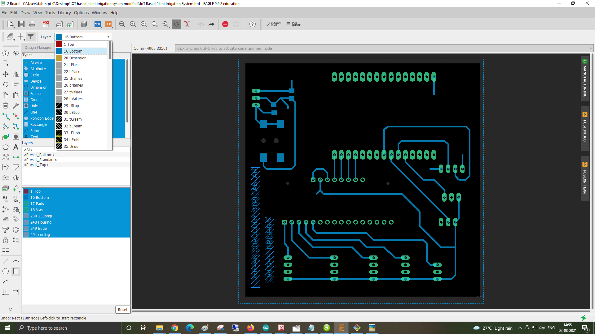
After this click on the to corner of the black pcb image and draw the rectangle covering whole pcb as shown in below images.
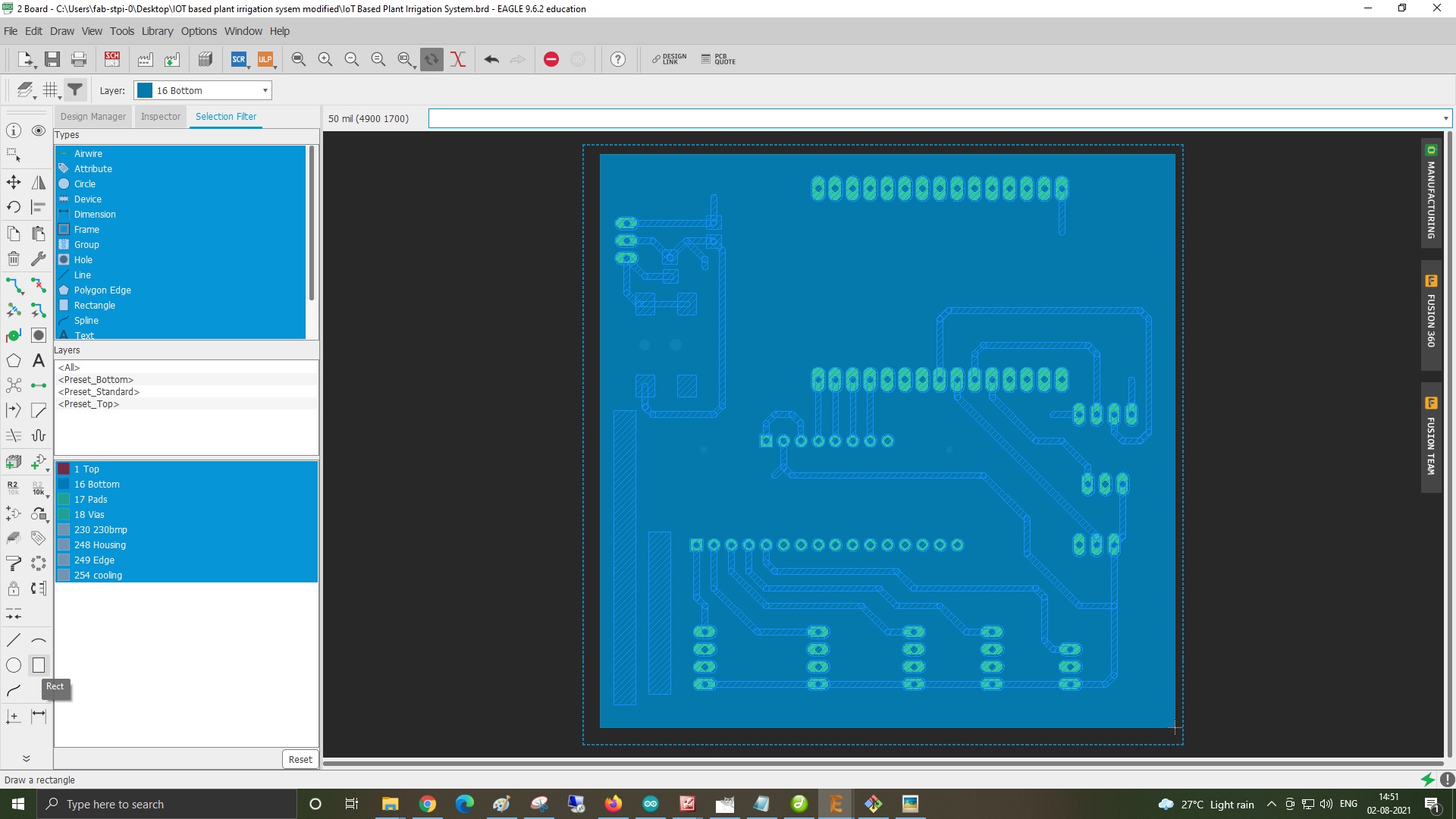
After this export as image in mono chrome 1000 dpi.
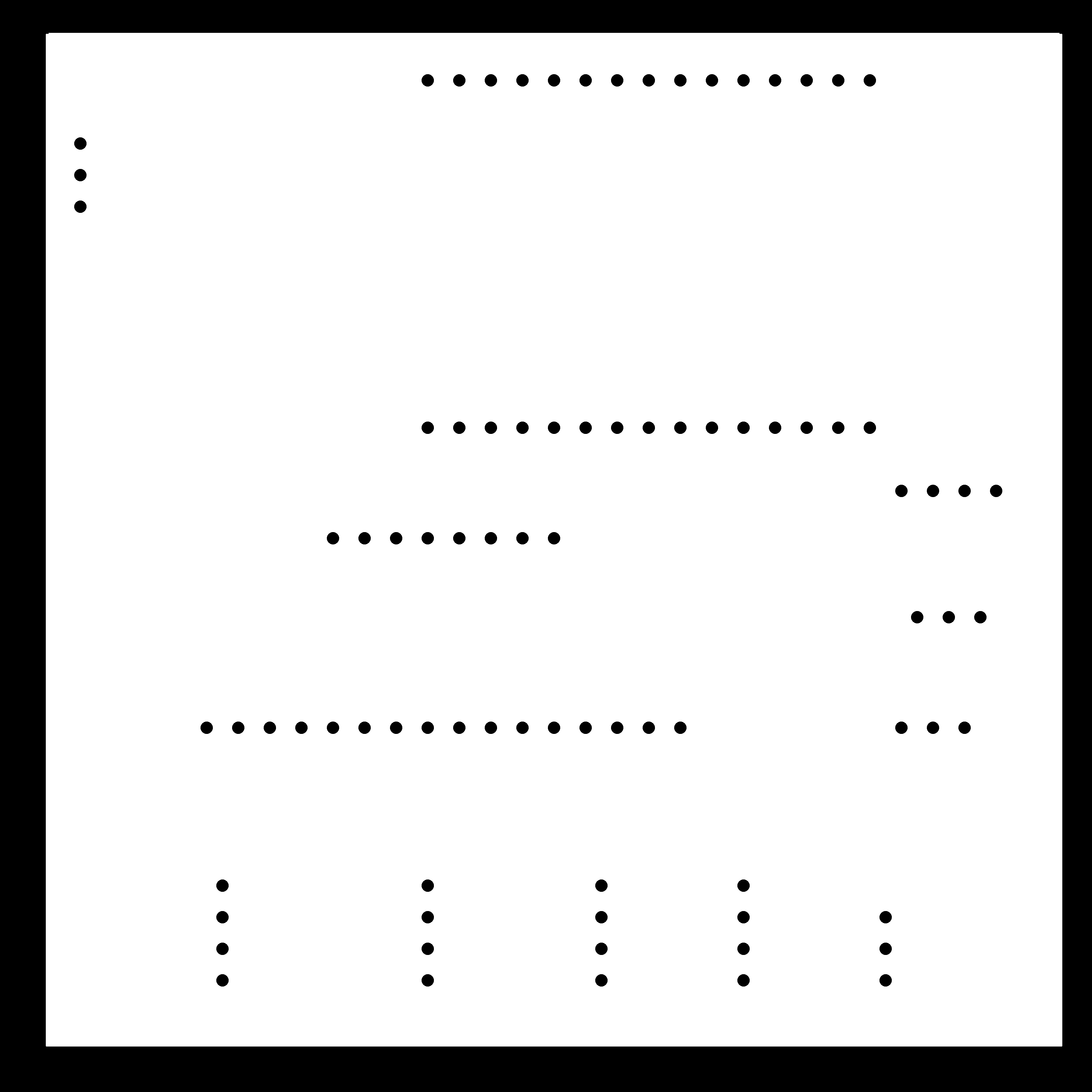
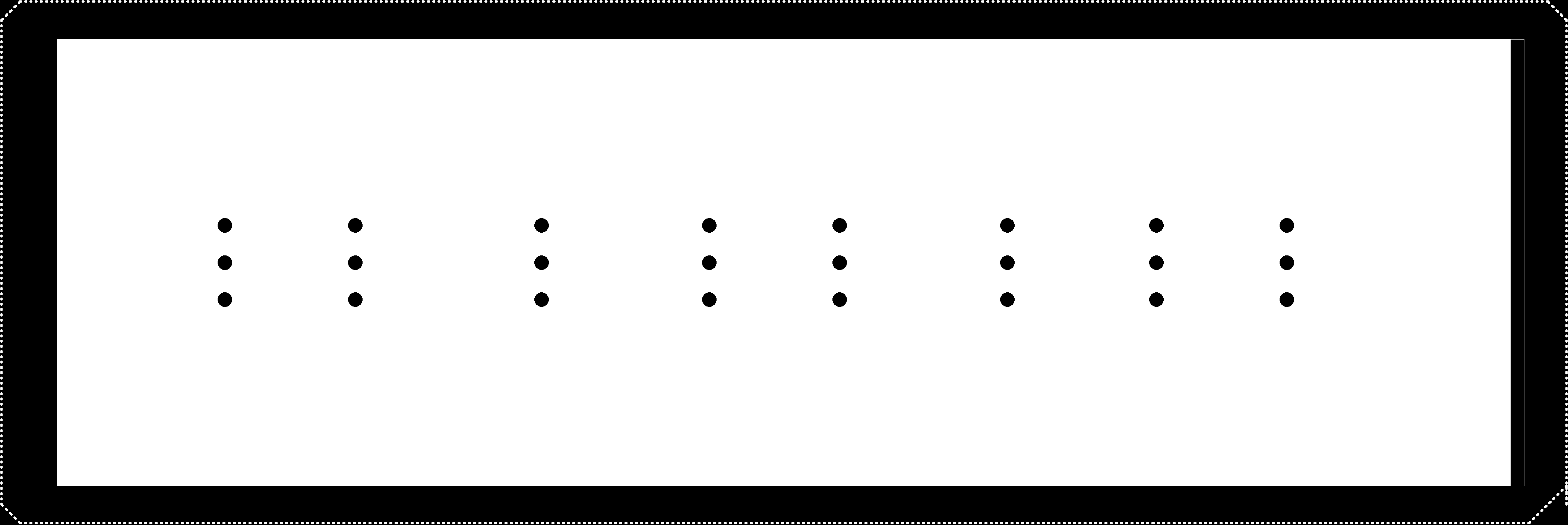
The holes file is as follows
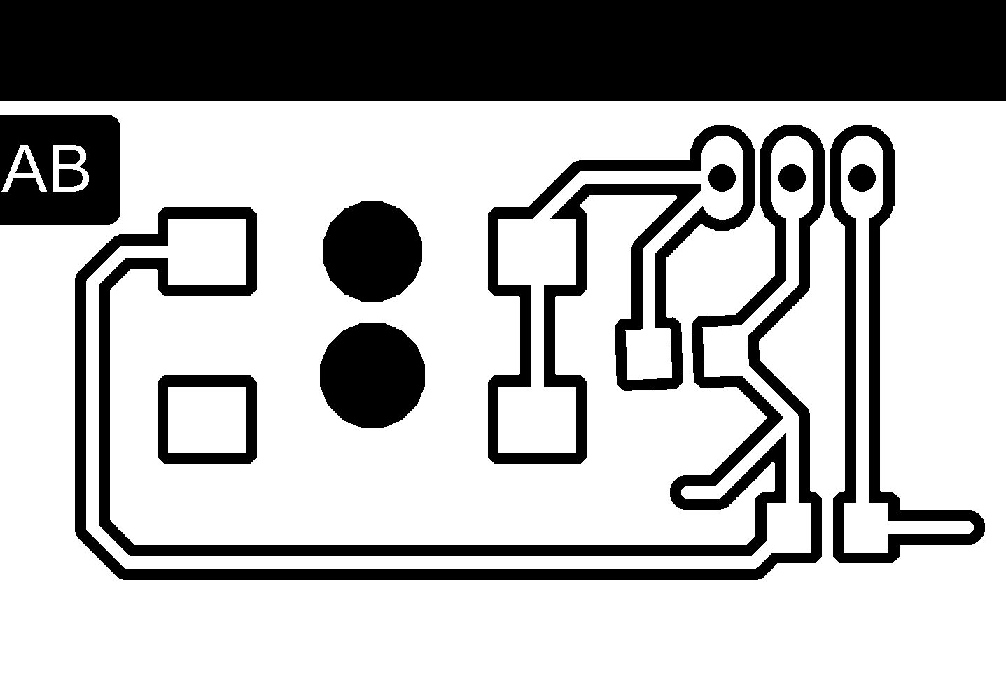
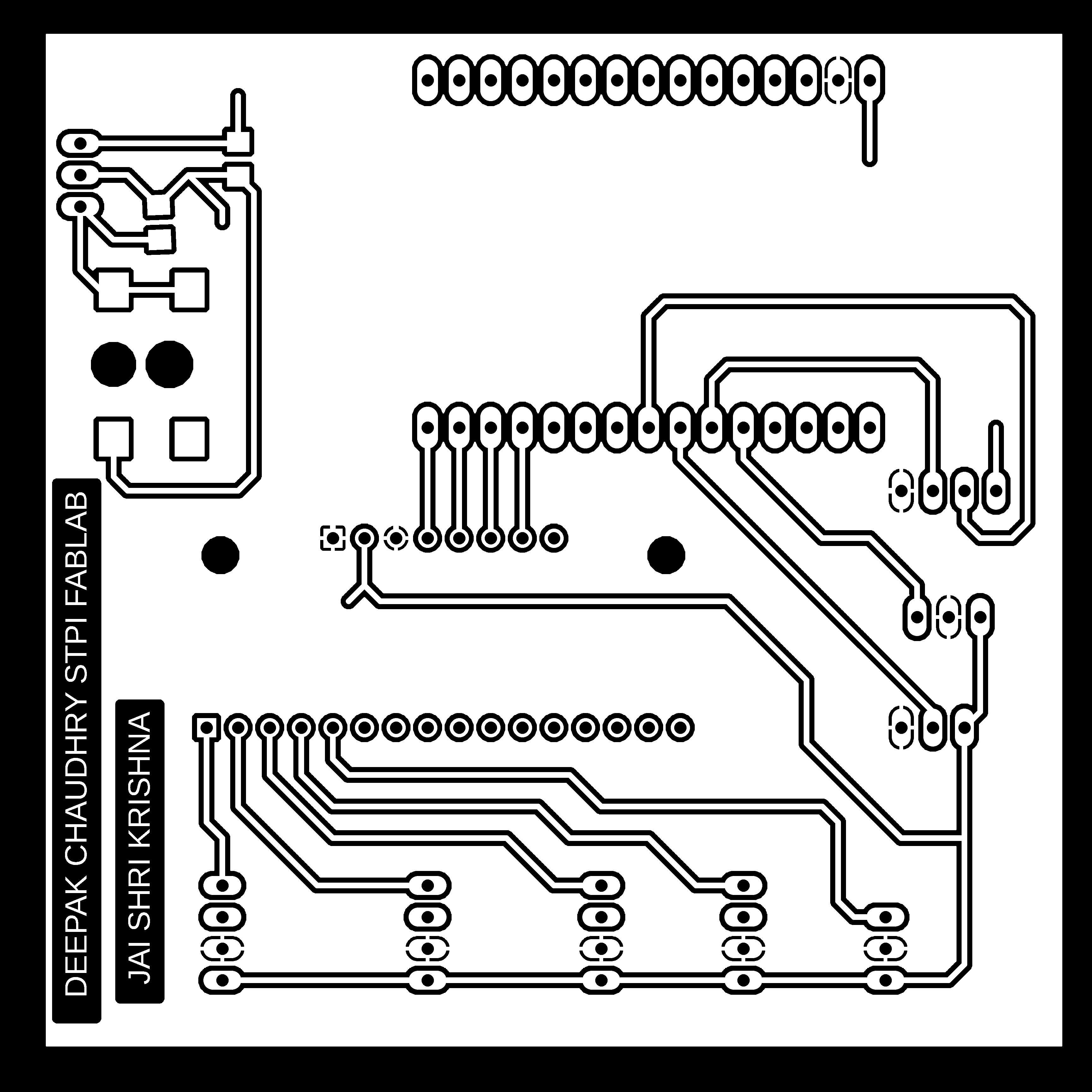
In the trace file designed the seprate power circuit on the same board.This power circuit was isolated from rest of the circuit to safe guard gainst the arbitary voltage that may be supplied to the circuit.after measuring the required current from the circuit i included it in the mail circuit using the jumper wire.
After this i milled the circuit after creating the rml fils from the traces.png and holes.png
After this i milled the traces and holes on the milling machine. and soldered the female headers.
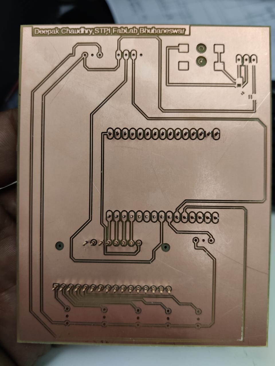
There was some some traces problem and pad problem in the pcb. So i again milled the pcb and soldered the female headers which looked like this and assembled the components.
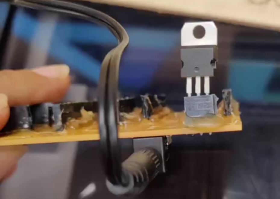
After this I tested the power circuit i gave the external power to the board through the Vin pin of the node mcu.The reason for giving the external power to the board was that all of the sensors and the relay board were requiring the 5v volatage. I am using the regulator IC 7805 for 5v supply from the 9v adapter available in the fablab.
i am using the dc submersible pump for supplying the water to the plants. So i designed another power circuit to derive the motor to pump the water to the flower pots. DC motors during the normal startup withdraws the high current isrrespective of the normal load which may hinder the supply volatege to the other components.
Fo this i designed the another power circuit. using eagle cad

After this i soldered the components and tested the output current it was giving 4.9 V as per requirement
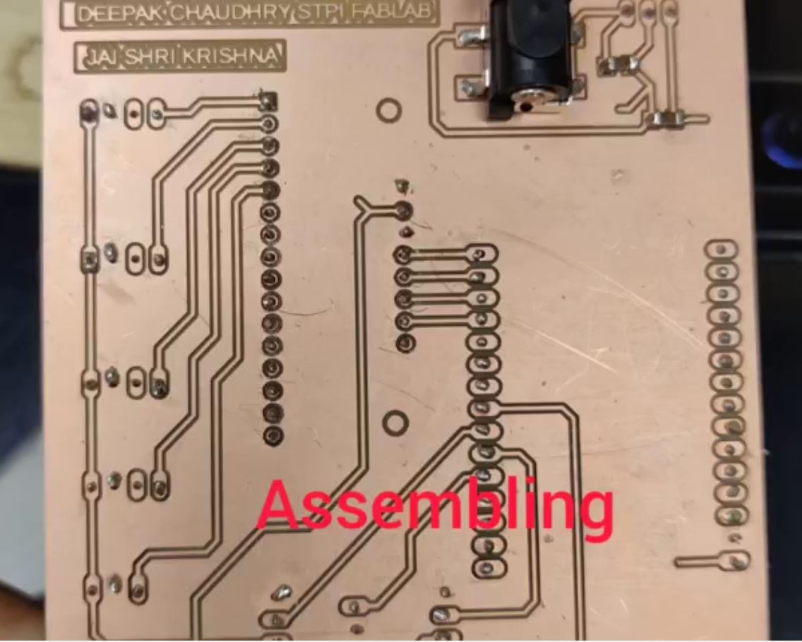
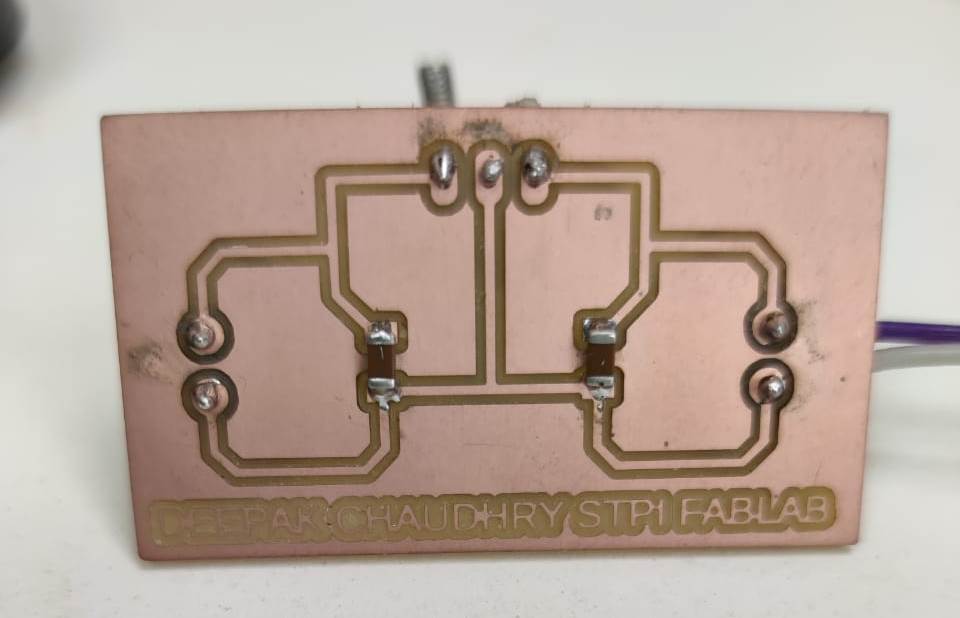
As my project was to be closed in the enclosure i had to create another pcb for connecting the sensors and output of the relays.In eagle cad i designed the PCB and milled it.
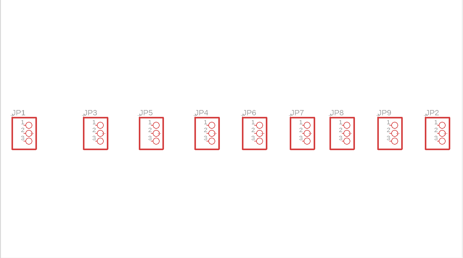

After milling this pcb i soldered the male headers to this.
.jpg)
.jpg)
after this i checked the board and the strip PCB
It was working fine.
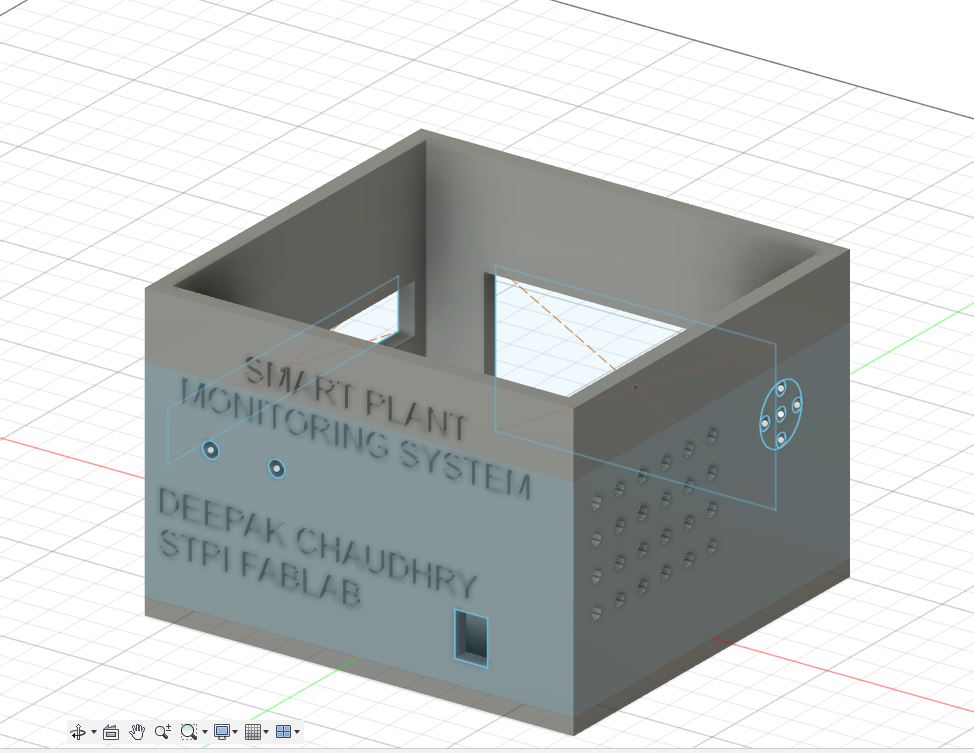
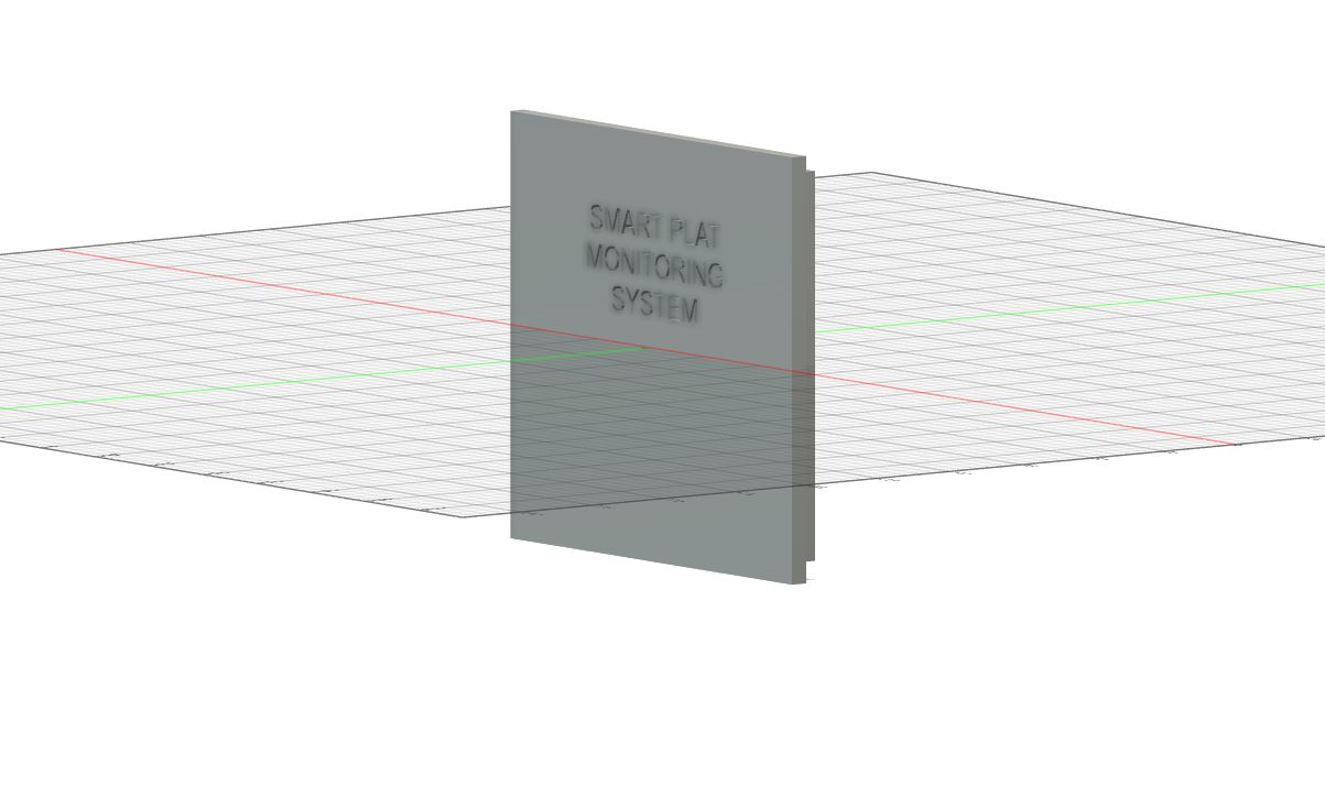
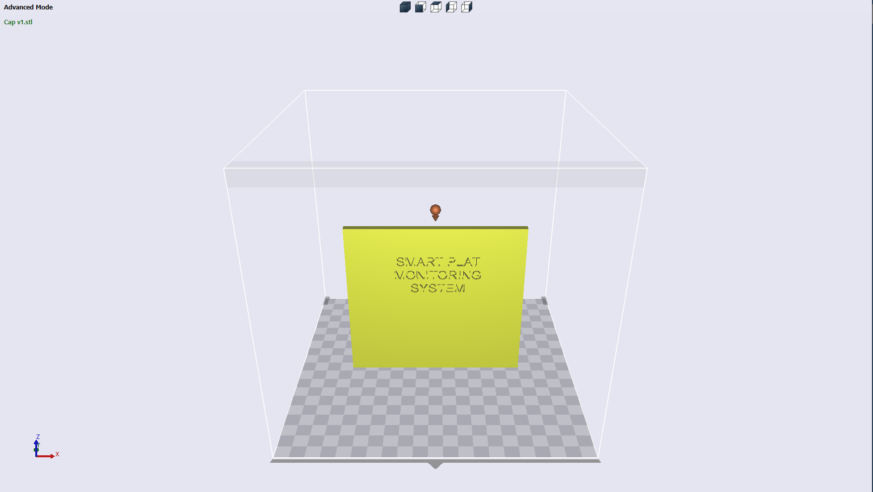
My next task was to create the 3d enclosure for this project.
I designed the enclosure in the Autodesk Fusion 360.
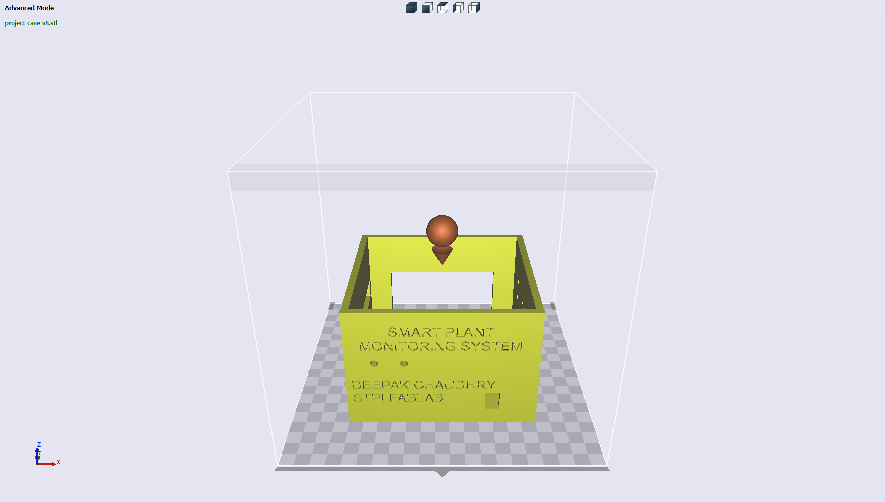
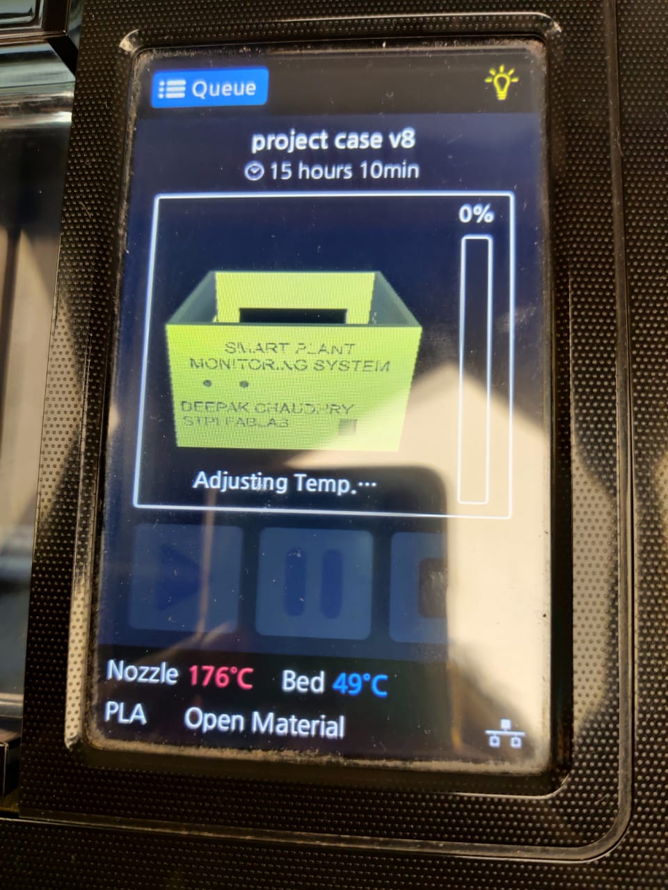
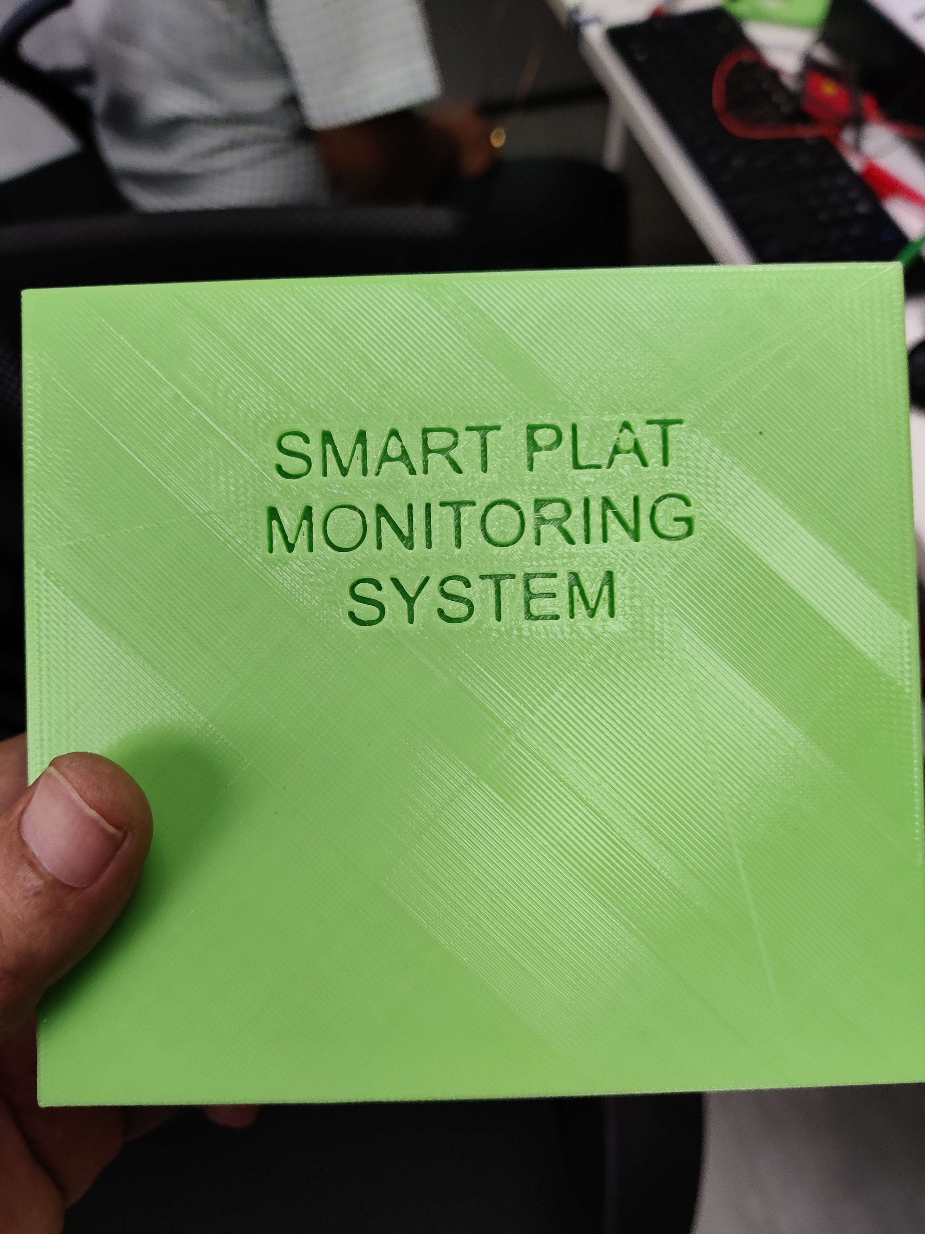
After this i printed the box in the Sindoh 3D printer
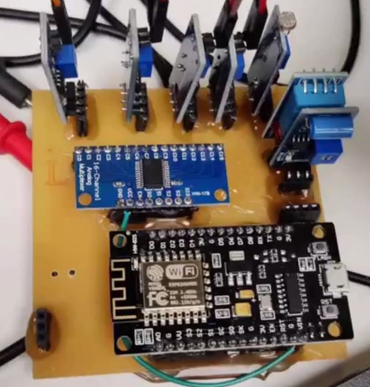
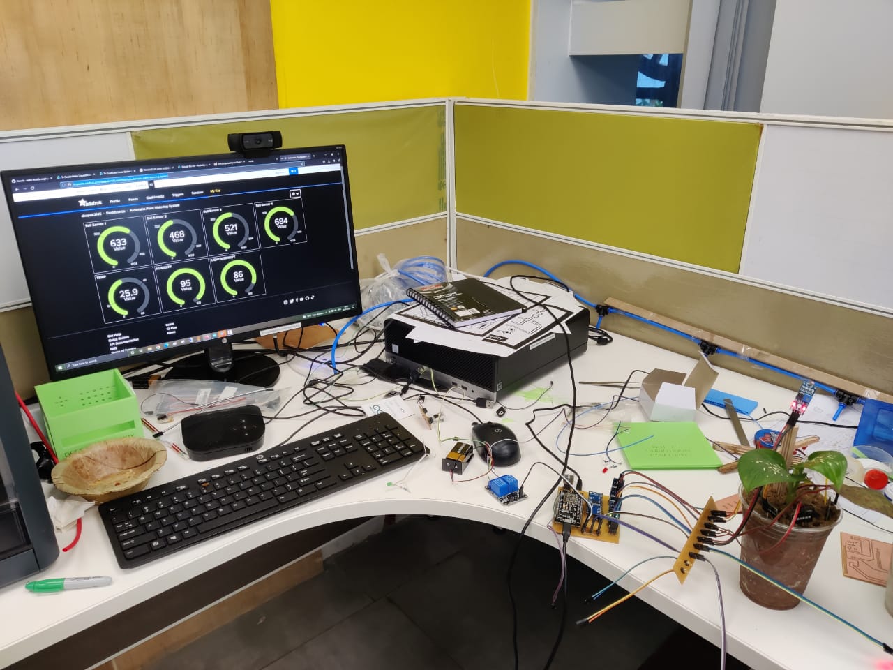
Afterhis i assemble the main PCB and the strip PCB in the box for testing
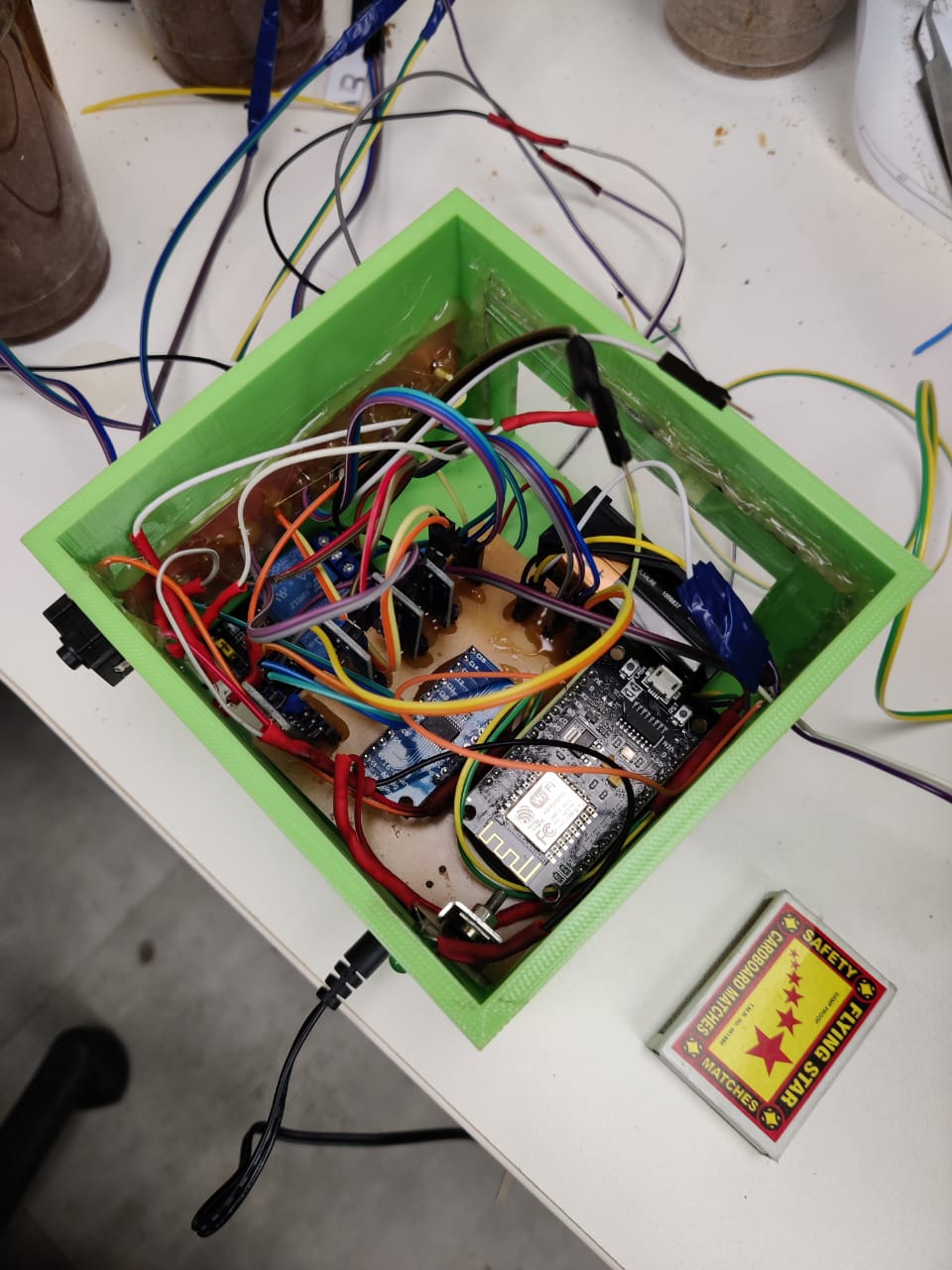
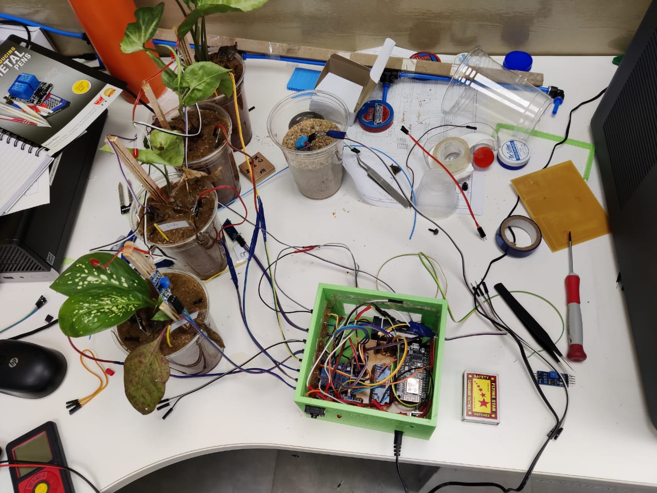
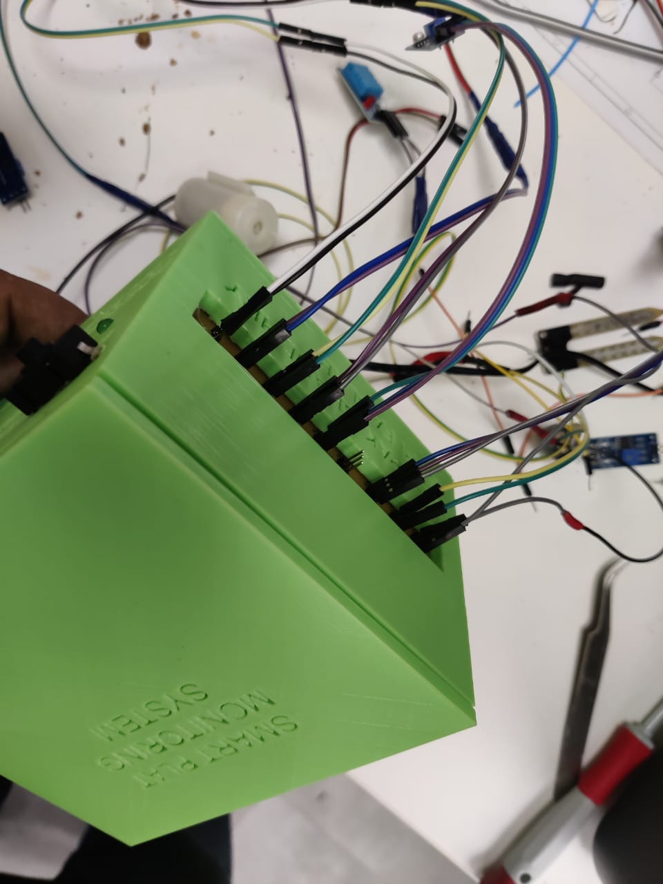
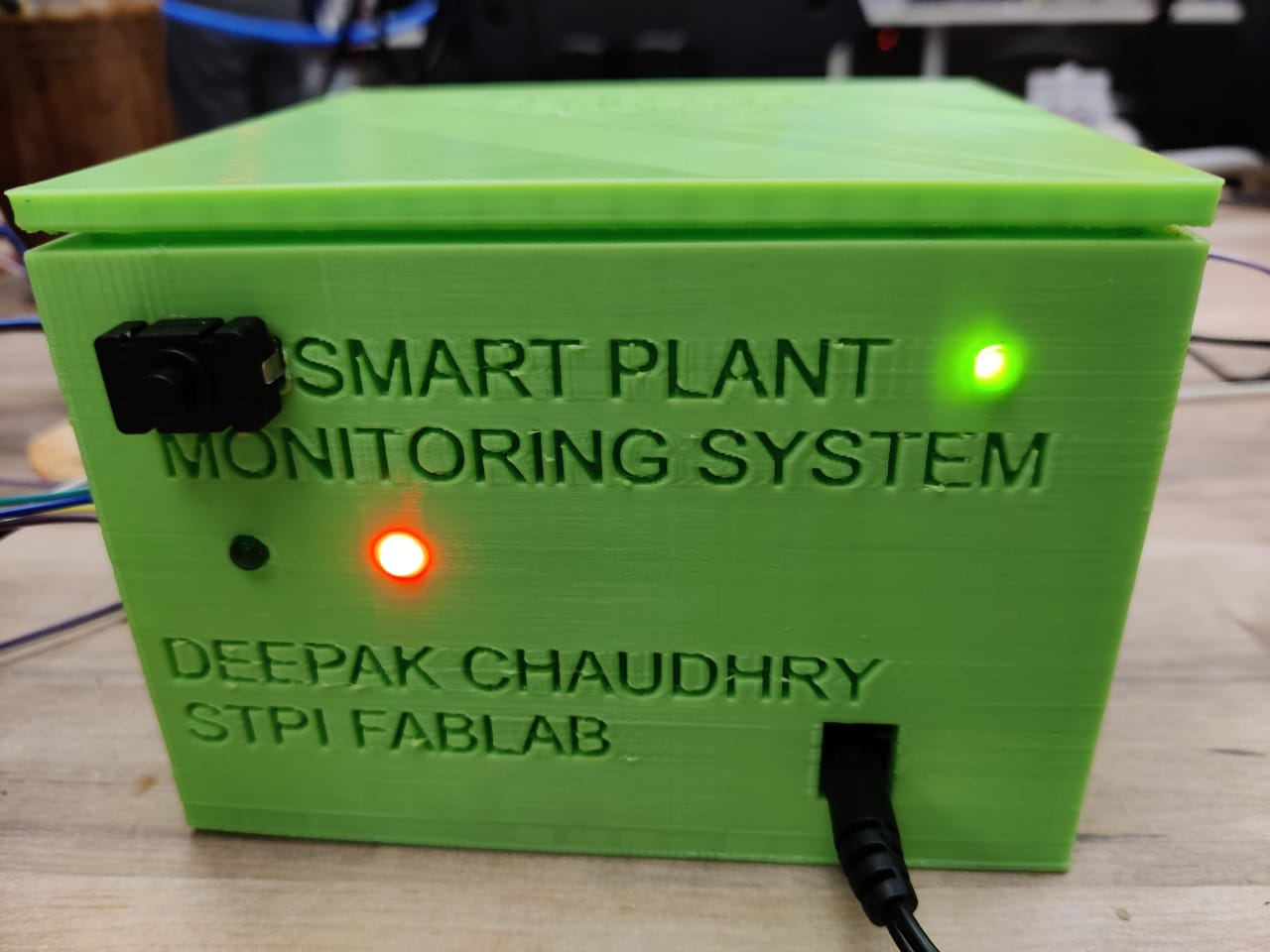
I supplied the box external power and assembled it.
The Final Project Files can be downloaded Here
My Second idea was to make something electronics based device This will be helpful for the stroke patients who lacks in motor disability.Who cant move his limbs.
.Thsi may be helpful in training them. Soon i will post. about the design and try to make it.
My third idea was to make the POV (Persistence Of Vision) display.